|
|
|
|
|

|
|
And Inventory Management System Photon Map Page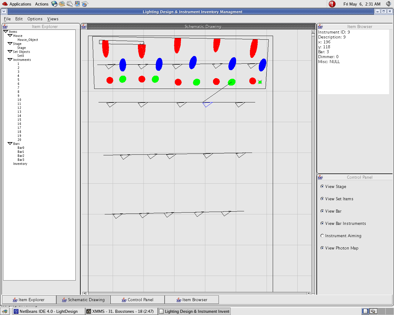
Overview:The Theatrical Lighting Design and Inventory Management System was created as a way to allow Lighting designers to easily create a design that can be used by electricians in a theater to properly set up lights. The software has multiple parts that help get to this goal. The GUI driven interface is designed for theatrical lighting and allows quick creation of theater spaces so lighting designers can get to designing lights quicker. The inventory management system allows for the user to quickly know what instruments are available to be used in a design. The main focus of this page is geared towards the usage of photon maps to allow designers to see light interaction with set objects and other lights. Also the cue editor will allow designers to change levels of instruments to test light interaction of their design in a more realistic setting. The software was written in JAVA to allow for lighting designers to use any computer system to develop lighting designs. Problem:In theatrical lighting, a lighting designer is responsible for creating the look and feel of the lights. In normal operation it is hard to visualize how the design will look without actually having everything set up. To setup a fully implemented lighting plot in a theater is a labor intensive and time consuming process. The need for a way to test designs without using up time of labor and time in the theater is apparent. Goals:The Theatrical Lighting and Inventory Management System enables lighting designers to create a virtual lighting plot and be able to test the usability of the lighting plot. The goal for the usage of photon maps within this project are to allow the user to quickly be able to view the area the light will affect and also to interactively test the lights at different power levels. The desire for interactive speeds is paramount within this effort to allow for constant design time with no long delays for rendering potential designs that only will be scrapped. A secondary objective is accurate representation, while there are methods to fully render high quality images with multiple light sources they take a long time to create the images. With these concerns in mind the challenges that must be overcome are to take into account multiple directional light sources within large overlapping areas and the ability to change power levels of the light sources at interactive speeds. Process:The Theatrical Lighting Design and Inventory Management System uses a GUI driven interface of a top down 2D schematic view of the theater area to position the stage, instruments, set objects, and bars. Using further information provided by popup windows all the data needed to recreate a 3D representation of the theater space is acquired. This information is stored internally within the program and can be outputted to xml files linked to a project file so a user can recall the data at a later time. Photon maps are all stored internally within the program although a method was created for saving photon maps to xml but they are so large files they are not practical to use with the needed number of photons that need to be recorded. The photo map used to record the lighting intersections is slightly modified to try an achieve the goals of the program. Instead of using the normal 2 pass method of photon map that renders at non interactive speed a one pass method is used. The one pass method uses raytracing to calculate the intersections of light photons with the set objects. The major changes to the raytracing algorithm are that no caustics are recorded or calculated because they are not necessary for theatrical lighting and take to long to calculate. Also the number of reflections off set objects are reduced from normal amount used in photon map ray tracing to allow for more data to be gathered from the original light source. The data recorded within in the photon map has also been modified to accommodate our goals. Firstly a maximum number of photons must be set for memory constraints and photons are spread out equally among each light source. The method is modified a photon stores data representing the point of intersection with a surface, the angle that the light hits at the intersection, the color that the light would be at that point of intersection, and which light source the photon came from. The information within the photon maps are used in two places within the program. On the main schematic page the photon map can be made visible visible as a straight overlay of photons onto the schematic. This allows for quick checking of which set objects the lights will hit and how much area the light will project upon the stage. In the cue editing view photons are placed in to an image map sorted by which light source it originally came from. This will create an image of the light projection in the x,z plane for each light source. For each pixel in the final image the color value from each image map is added to the final image map with consideration taken for the power level of the light the image map represents. The end result is a good representation of the light interaction with each other and the set objects. Results:The usability results are quite good in allowing a lighting designer to visually see where the light are placed and how they interact within the created design. Performance speed is an increase from using a two path method but the quality of the image is not as good as the quality of a two pass photon map method. The speed increase is the major benefit and worth the degradation in image quality. On a 1.2ghz processor with 512mb RAM running Linux Fedora Core 3 it takes 20 minutes to use the unmodified two pass method to render a scene with two lights sources. A more complex scene with 4 light sources within the Theatrical Lighting Design and Inventory Management System took only 5 seconds to originally calculate the photon maps and takes less then 1 second to overlay the photon map onto the schematic. With the same scene it took 1 minute to calculate the individual light source images and less then 2 seconds to render the scene with changed levels. The change in levels of the light is the most speed increase because with the original two path method with no light source data stored in photons it has to render the entire scene again from scratch if a light source's power level is changed. There are some problems with the current system. Because the amount of light sources can be vast and the area the lights cover can also be large the number of photons that could be necessary to fully cover the area covered by the light source is larger then the system can handle. Since there are not enough photons to go around gaps can be seen in between the intersection points of photons. This could be compensated in the cue editor by calculating each pixel in the individual light source images with consideration to surrounding pixels. Also even though there is a dramatic speedup compared to a photon map using caustics and two passes the speed up could probably be faster with this method if it was not integrated into a JAVA program, but then the systems would not be able to be used across a large number of operating systems. Development Process:During the creation of photons maps within the Theatrical Lighting Design and Inventory Management System (TLD&IM System) there were many trial implementations before the end result. Here s a description of the development flows that was gone through before producing the final product. The design for the original program was an external program that would read in the saved xml files from the TLD&IM System. The original design included a 3D camera view that would be changeable upon original calculations of the photon maps but remain static from that point. It would have included the sliders similar to the Cue Editing view that would change the power levels of the lights. During the design phase the open source sunflow global illumination project was found and looked over for research. Based off the research the original photon map storage was only going to be an array of unsorted photons that held information about the intersection location, originating light source and the color after calculating the normal of the surface and angle of reflection that the light hits. To calculate the photon maps the light sources were represented as points with a direction of view and rays were projected in to the scene with a random variation with in a radius of 1 unit along the direction vector. The intersections were calculated and then reflection vectors were also projected at random angles inside the scene. The plan for rendering the photon maps was to create multiple image maps based off of which light source a photon originated from. The image map was going to be created by casting rays from the photon locations to the camera to find which pixel the photon would be contained in on the final image plane. The individual image maps would then be added together to create realistic light interaction in a final image that the user would see. During development of the original design many problems arouse. Photon maps creation was not intersecting anything and when it seemed to work the photon map array would create a java.lang.OutOfMemory error while only using a couple thousand photons. Also the color at intersections with objects always appeared the same value when looking at the photon map in memory, this could have been because of rounding errors with not enough variation in rays or caused by the fact that all the sides in the scene were perfectly horizontal or vertical. Also the generation of the image maps always came out black for an unknown reason. The problem could have been not creating the camera correctly or trying to detect which pixel the photon should be on. Because of these problems a design decision was made to try and integrate in the sunflow global illumination project into the problem areas of the cue editing program. To integrate in the sunflow global illumination project the problem areas that were identified were the camera rendering, color deciding at intersections, and the math for calculating were rays intersect planes of objects. The attempt to just add straight in the files from the sunflow program and meld them into the cue editing program turned into a huge mess. In order to work in the calculations for rays intersecting planes used by the sunflow program the functions for how to create objects had to change and additional conversion functions were made to change data into what should have been correct formats. Then unconversion functions were created to transfer the sunflow data back into data the cue editing program used. Similar things had to be done to try and integrate in the pinhole camera class within the sunflow program. Also the color deciding algorithm was closely tied to the state class found with in the sunflow program and resembled the current one being used so it was left unknown why it didn’t work properly. Upon creation of the conversion functions the program run time increased drastically because of all the float and double math that had to be processed for each photon being rendered and also incorrect data seemed to be getting into the photon map. The incorrect data was probably due to an error within the conversion functions but after hours of debugging the problem could not be found. Also the data that was present was getting mapped to a single pixel in the camera and this error was not able to be found using debug tools. It was time for another possible redesign decision. The decision was made to try and use the open source code of the sunflow global illumination project more extensively. First an ad hoc xml parsing function was used to try and load the saved data into the sunflow program and check to see if it would render the data. This effort failed and no image was ever produced. Later issues were found in the ways set objects were being converted from planes represented by 4 to 15 points into triangles so this might have been the start to an issue that grew larger but the reason was never found. The focus turned from just seeing if the program would work by it self to how would it work with just modifying the open source code to work as a cue editor. The next major hurtle was getting the photon map to be stored correctly. The additional information about the originating light source was added into the photon map class and ensured that it would be passed along during light ray calculations. Also the caustic map functions were commented out because they were not desired to be used. Also a special xml scheme was designed to hold the necessary parameters to render the scene in an xml file. The program was run again with no manipulations on the rendering side and the photon maps were successfully made and were able to be saved to xml in multiple files to accommodate for the size of the photon map list. Unfortunately the display still would not render the scene. The next issue was why the camera was not rendering anything but more importantly to modify the rendering to render faster then it was previously and be able to control light levels without recalculating the photon map. To accomplish this, the old rendering functions were commented out and the designed one implemented. Rays were traced from the photons to the camera to find which pixels they represent. The pinhole camera call was modified to support multiple image maps for the each light source. Then the photon’s color value was assigned to that pixel inside and image map associated with a single light source and all the photons emitted from it. The images maps then were added together to create a final image and displayed to the screen. Unfortunately the same problem, of the photon maps being valid but nothing being rendering into the individual bitmaps was happening. After hours of debugging there was still no image appearing in the image maps even though values in the photon map were valid. It was determined the problem was in the code for translating into the camera images and would need a whole rework to of the way the system was working to work properly. A finally big design decision was made to switch the program from stand alone and integrate it into the Theatrical Lighting Design and Inventory Management System. To integrate the system into the TLD&IM System the modified files for creating photon maps was mixed with the source code for the original TLD&IM System. The easy GUI interface to add 3D information was added and there was no data transfer to xml any more. The data was translated straight from the data containers into objects useable by the photon map generation code. The same design idea was used but was first done in the schematic view to test the photon map creation against the objects that were represented on stage. Then the Cue Editor window was created and instead of using a camera to render photons in a 3D view the photons were rendered on the x/z plane. It was found by doing the depth of a pixel in an image was lost and an artificial color of lights that do not intersect in 3D but do on the x/z plane can be combined even if they are blocked. It was apparent this problem could have arisen in the previous design when the second pass was removed. After adding control for the power level of the lights it was determined the rendering was still to slow and a render button was added and the final image would only take into account the power level changes when the render button was pressed or the cue editor was started up. After a few bug fixes and feature flaw corrections the current Alpha1 release came into being. The latest bug fixers contained a problem with loading set objects, color when two lights occupied the same pixel and a new algorithm that checks if the pixel is already occupied by a photon from the same light source. This seems to almost double the time to render the photons, but the overall affect after the initial rendering is still the same so it is acceptable. Source Documentation Used in PhotonMapping:Open Source Files Used (package:file/source/description): Open Source Files Modified (package:file/source/description): Original Source Files (package:file/description): Future Work:There are still many improvements that can be made to usage of the photon map usage within the Theatrical Lighting Design and Inventory Management System. The following section describes what some of these could be: Area between pixels: To limit the amount of area between pixels a system needs to be developed that can either sample areas then fill in the color, but we loose data or soften around the pixels but then we are placing soft data where there really isn’t any. Either way there are tradeoffs but right now it does not look all that great having the gaps between the photons and leaves some ambiguity. The current version attempted one fix at this by only limiting one photon per pixel per light source. While this limits any future work on computing intensity based off of number ofo phtons and increases the time it takes to render the photons if the radius is of lights are small the whole effect looks better. 3D Cue Editor View: It would really be nice to have the cue editor from a 3D view, but in order to do that the stage and set objects will also have to be drawn so there is reference to what is being looked at. Saving/loading Cues: Being able to manipulate power levels is great and all but being able to save and recall or able to send them to someone else would be a huge benefit and hopefully soon will be moved to the features list. Simulating Gobos: If you could select an image map as a gobo for a light it would be useful in seeing how the gobos become distorted as they are expanded by the light and hit set objects. So using an image map to filter the area the light rays can pass through would be some very possible addition in the future. Add depth data to image maps: Add information to the image maps that also tell the depth of a pixel to see if it should mix with other image maps or add a visible or not information to see if the user can see it or if something is blocking it on the x/z plane. This is missing because it is usually determined in the second pass of Photon mapping which has been removed in this version. Examples of XML Data:Photon Example: photon x="103.80893" y="96.0" z="19.730536" nx="0.0" ny="0.0" nz="0.0" dx="0.0" dy="0.0" dz="0.0" power="-1778384656" r="0.0" g="0.0" b="1.0" light="0"/ Set Object Example: set name="Set0" description="NULL" id="0" house_id="House_Object" x="23" y="20" z="600" node x="0" y="0" z="600" node x="0" y="10" z="600" node x="683" y="12" z="600" node x="684" y="5" z="600" /set Instrument Example: instrument name="NULL" description="50" bar_id="3" type="striplight" x="106" y="46" z="200" inventory_id="50" dimmer_id="0" aimX="130" aimY="27" aimZ="75" colorR="1.0" colorG="0.0" colorB="0.0" radius="50"/ Citations:The original photon map program modified within the Theatrical Lighting Design and Inventory Management System and used for software measurements testing. can be found at: http://sunflow.sourceforge.net/ Research Papers: Global Illumination Using Photon Maps by Henrik Wann Jensen Design And Simulation of Opera Lighting and Projection Effects by Julie O Dorsey, Francios X. Silhon, Donald P. Greenberg 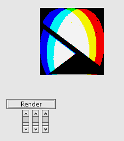
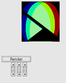
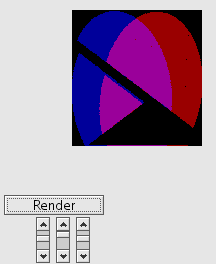
Three pictures showing the interactions of lights wiht each other in the cue editor 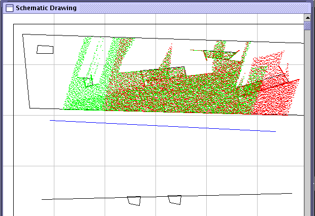
Picture showing how the lights interact with set objects in the schematic view. 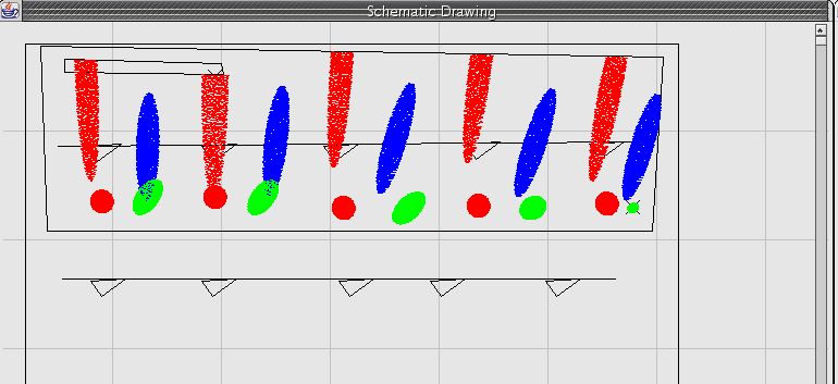
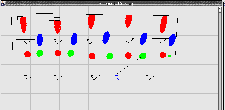
Picture showing how the lightint calculation when teh radius of a light is changed in the schematic view. 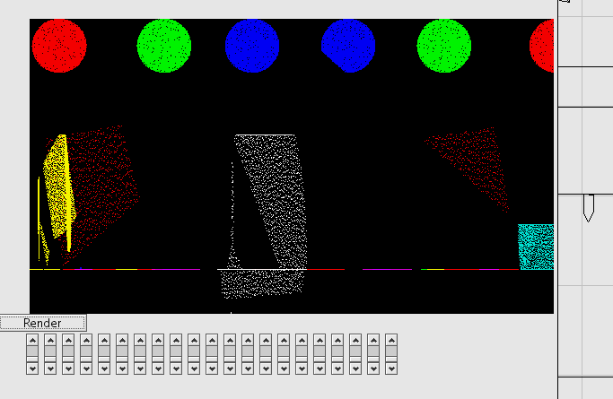
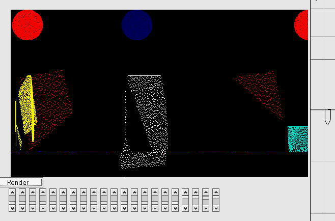
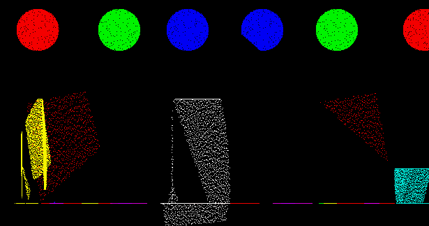
Pictures shwoing the cue editor in action and the iamge map that can be saved from the interface created by Joshua Zawislak 05-09-2005 |